KEY CAPABILITIES – CIVIL- 3D
A. OPERATIONAL AREA:
- Land development
- Residential land development
- Commercial land development
- Plot plan
- Cad Conversion
- Potable Water & Wastewater
- Transportation
B. SERVICES:
- Residential Land Development
- Base file Generation (Lot Plan)
- Tentative /Preliminary Plan
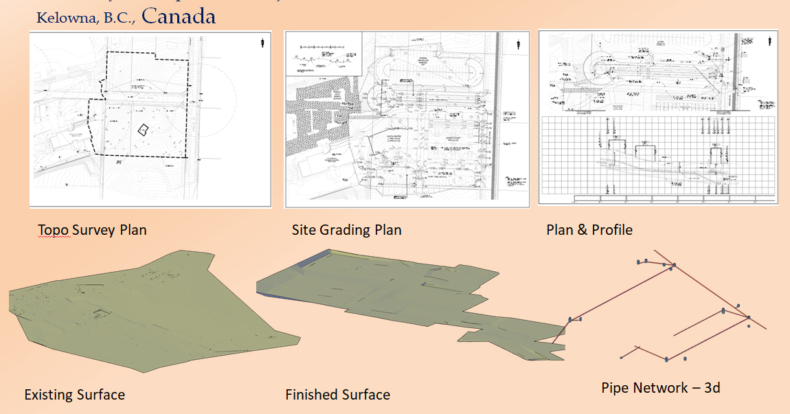
- Grading Design
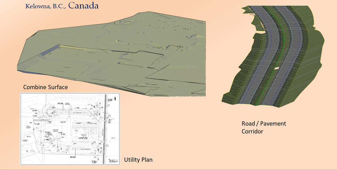
- Paving Design
- Drainage Area & Hydrology Studies
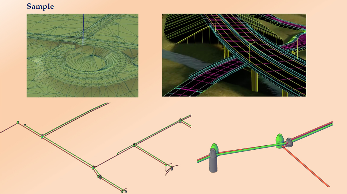
- Storm Drain Design
- Sewer Design
- Plan & Profile Sheets
- Final plat
- Material take-offs or cost estimates
- Plot Plan
C. Commercial Land Development
- Rough Grading
- Precise Grading
- Preliminary Drainage Reports
- Storm Water Pollution Prevention Plans (SWPPP)
- Demolition & street widening plans
- Utility Plan & Profiles
- Storm Drain Plan & Profiles
D. Cad Conversion
- Preparation of plan, section, elevation and sections
- Ability to accurately capture old, smudged and dense information from paper sources
- Capability to convert thousand hours‟ worth of information into accurate and precise CAD files
- Skilled draftsmen working under domain experts to convert with consistency and diligent QC
E. Hydraulic & Hydrology Studies
- Pond Design,
- Flood Modelling
- Storm Drain Modelling
- Rainfall/runoff studies
- River/channel studies and Modelling
- Storm water quality impact and use of Best Management Practices (BMPs)
- Wash grade works, Urban flood Modelling
F. Public Works
- Lift station
- Road widening
- Pavement relocation
- Water treatment plants
- Wastewater treatment plants
G. Transportation
- Survey maps, strip plans, and existing surface profiles
- Digital terrain modelling
- Alignment design
- Intersection design
- Pavement design
- Drainage design
- Earthwork quantification
- Plan and profile sheet generation
PROJECT SHOWCASE– CIVIL- 3D
A RESIDENTIAL LAND DEVELOPMENT:
PROJECT: Design the Land development and associated services for a Residential Project in USA
Scope of Work: This project needs the execution of the following tasks–
- Preparing a preliminary utility layout (layout of sanitary and storm sewers and waterlines) over the lot plan (plat file).
- Preparing preliminary quantity estimates (material take-offs) for the project area.
- Preparing base file by using city standards and client standards.
- d)Designing lot grading and computing cut and fill information of the project area.
- Preparing of drainage area map.
- Hydraulic calculations for the project area using the software WinStorm)
- Preparing plan & profile sheets.
Input:
- Preliminary lot plan(plat file)
- Survey info (topographical features & existing utility information) of the project area.
- City design standards.
- Client CAD standards (sample project, preferably one executed in the same city as the proposed project)
Output:
Phase-1
- Preliminary base file(with sanitary, storm, and water layout)
- Preliminary hydraulic calculations (HGL line, storm, sewer sizes and inlet sizes) by using WinStorm data
- Quantity estimates (material take-offs)
Phase–2
- Updated base file
- Lot grading plan with top of curb elevation
- Cut & fill information
- Drainage area map
- Water & sewer layout
Phase–3
- Hydraulic calculation sheet (generated using Win-Storm)
- Plan and profile sheets (showing profiles of existing ground, top of curb, sanitary sewer, storm sewer and water line)
- Final quantity estimates (material take-offs)
Software Used:
- Auto-DeskCivil-3D
- AutoCAD
- Microsoft Excel (For Calculate FL value of Sanitary Sewer)
- Win-Storm3.05, 2002
PROJECT: Design the Roads and associated services according to Department of Main Queensland Road Planning and Design Manual
Scope of Work: This project needs the execution of the following tasks:
- Design of intersection of McIlwraith Road and the Bundaberg- Gin Gin Road (Design is to be in
- accordance with Department of Main Roads Queensland Road Planning and Design Manual).
- b) Design of internal road within the subdivision in accordance with Austroads Rural Road Design.
- c) Preparation of internal Road plan and L-Sections, Intersection details,
- d) Drainage details, Services plan, Cross-Sections
- e) Earthwork Calculations
Input:
- Layout plan
- Survey info (topographical features & existing utility information) of the project area.
- Traffic Impact Assessment Report and photos
- d)City design standards.
- Client CAD standards (sample project, preferably one executed in the same city as the proposed project)
Output:
- Traffic analysis
- Intersection Design
- Plans, L-Sections, Intersection details, Drainage details, services plan and Cross- sections
- Cut & Fill Information
Software Used:
Public Works
PROJECT: Creation of “Base sheets” With All Existing Topographical Features (Natural & Man-Made) And Utilities.
Scope of Work: This project needs the creation of “base sheets”. Essentially a base sheet is a P&P sheet with all existing topographical features (natural & man-made) and utilities shown in both plan & profile views. The topography at the project site has been mostly raw land and there were few existing underground utilities or above ground entities that constrained design.
The Client send comprehensive survey data of the project area (often in an urban environment) and we exhibit the given survey data on plan sets.
Given below is a brief overview of the project:
- The Client sends to us an ASCII file that should be rendered to a DWG file format using LDD. The points in the DWG file format are coded (“FV” for fire valve, “TC” for top of curb, “GL” for gutter line, “DW” for drive way, etc.)
- WE creates a plan view “picture” of what the actual conditions look like on the ground by connecting the points in LDD and creating a map which also shows plan views of underground utilities.
- WE then creates profiles of paving and utilities, based on the point data that was used to create the plan view.
Input:
- ASCII file with survey data
- Point description files that will need to convert the ASCII files to a DWG file format.
- A video drive-by of the project site to further help understand what the project site actually looks like.
- Measure-down notes made by survey crews by opening manholes to get flowlines, pipe diameter, and the direction of pipe run, for both sanitary and storm sewers.
- A sample set of plan and profile sheets with the existing entities shown to illustrate to what the final product should look like.
- The CAD standards of the client, instructing about the graphical elements in the drawing (layers, font sizes, line weight etc.)
Project Steps:
- Study of the area from video file
- Study of point description file to understand all line items
- Creation of base file from ASCII data (survey data and point descriptions), using the video file to understand the terrain as and when required
- Redlining of base file
- Creating profiles for existing features:
- Creating natural ground (left, right & center) using existing surface
- Creating existing pavement gutter (left, right) using survey data.
- Creating existing storm and sanitary sewers using measure downs
- Creating existing water lines using existing record drawing
- Creating plan and profile sheets for existing features
- Redlining the existing features plan and profile sheets
- Studying preliminary design (proposed water line)
- Placing proposed water line in the base file
- Placing proposed water line profile in profile sheet
- Creating proposed plan and profile sheets
- Redlining proposed plan and profile sheets
Output:
- Cover sheet
- Index sheet
- Base file or over all file
- Individual plan and profile sheets
Software Used:
- Autodesk Civil 3d
- AutoCAD
D. Cad Drafting
PROJECT: Designing of 12 light rail transit (LRT) stations.
Scope of Work: Designing 12 light rail transit (LRT) stations to 65% completion, the submittal for which consists of plans, specifications, and cost estimate in compliance with Section
A. Design Submittals and in general accordance with Appendix
B. List of Anticipated Drawings of the scope of work contract. The 65% submittal is intended to represent a level of design sufficient to define the project and quantify its various components in order to prepare a reliable construction cost estimate. Herewith is the definition of the subject deliverables.
- Plans (drawing scales as noted on Appendix B; border and drawing names per CAD standards)
- Title sheet (based on PE Plan title, updated with WC and DEA logos, and designated "65% Design Submittal")
- Index of sheets (in format similar to PE Plans and based generally on listing in SOW Appendix B)
- Abbreviations (based on PE Plans, with updates and additions as required)
- Symbols (based on PE Plans, with updates and additions as required)
- Key plan (based on PE Plans)
- General Notes
Output: (Civil and architectural drawings) Drawing set consistent for each of 12 LRT stations, consisting of:
- Station Platform and Plaza Plan – Concourse layout (using revised RTD platform dimensions) and transition plaza boundaries; hardscape zones (paving areas, ADA strip, ramps, planters, pedestrian crossings, etc.); locations of shelters, highblock, wind screens, railings, walls, stairways, elevators; control tie to track stationing.
- Station Elevations and Sections – Longitudinal view of station platform and
transition to plaza, including high blocks, shelters, wind screens, railings, walls, stairways, etc.; and sections across platforms, track way, and transition toplaza.
- Platform Details –Platform layout, with locations of highblock, shelters, wind screens, railings, and hardscape zones.
- Plaza Details – Plaza limits defined, with hardscape and landscape zones, walls, railings, stairways, and any aesthetic features specific to each station location.
- Shelter Elevation and Section – Graphics, callouts, and dimensions of canopy shape and members, columns, foundations, materials; and any aesthetic features specific to a particular station.
- Station Structural Framing Plans – Platform, shelter, windscreen and other platform and plaza elements requiring footing design, located and dimensioned.
- Elevator Details – Elevator layout, dimensions, foundations, materials, and aesthetic concepts particular to location.
- Station Electrical Systems Plan – Placement indicated for electrical, video and data devices on station platform and transition plaza, dimensioned; with location of systems panel(s), pullboxes and conduit runs for station power, data, communication, and lighting circuits.
- Landscape Plan – Delineated hardscape and planting areas, denoting zones of turf, ground cover, shrubs, and deciduous and evergreen trees; pathways, walls, boulders and other landscape features may also be noted; point of connection for irrigation system will be indicated.
- Site Specific Details – High blocks, railings, wind screens, station lighting and other construction elements defined in terms of material, shape, general dimensions, etc, as necessary.
- Drawing set consistent for each park-n-ride (anticipated at Oak St and Jeffco Government Centre only), developed from final concepts by RTD, consisting of:
- Layout Plan – Defining with dimensions, the boundaries of paving and landscape, roadway access, circulation, raised islands for parking and/or bus drop off, and storm water detention basin.
- Grading Plan – Defined with control elevations to indicate drainage patterns and confirm access connections to existing roadways, including storm drainage system (in We and piping).
- Lighting and Electrical Plan – Placement indicated for park-n-ride lighting and security devices, dimensioned; with service connection, pull boxes and conduit runs for lighting and data circuits.
- Signing and Striping Plan – Delineating parking stalls and circulation control, with dimensions and symbols.
- Landscape Plan – Hardscape and planting areas, zones of turf, ground cover, shrubs, and deciduous and evergreen trees are delineated; pathways, walls, boulders and other landscape features may also be noted; point of connection for irrigation system will be indicated.
- Site Specific Details – Paving, curbing, signs, striping, and other construction elements defined in terms of material, shape, and dimensions.
E. Wastewater Treatment
PROJECT: Municipal Wastewater Treatment Plant
Scope of Work: This project involved the design of a primary sedimentation basin for a municipal wastewater treatment plant.
Input data:
- Average and peak design flows including recycled flows from downstream treatment units.
- Layout of treatment plant within the available project area, along with dimensions and contour information for the site, and the required shape of the basin.
- Influent flow characteristics, water surface profile through the entire treatment plant, influent pipe size and inlet structure, and HGL through the pipe.
- Catalogues from equipment manufacturers for providing appurtenances for the facility.
- Information on origins of all recycled flows to the head of the basin.
- State regulatory authority-specified design criteria. Project Steps:
- Basin geometry and sizing was decided upon based on flow information and criteria for overflow rate and detention time.
- Influent pipe and inlet structure were selected based on allowable head loss and other considerations.
- Effluent structure was designed. V-notch weirs were provided and their depths checked against the head at average and peak design flows.
- Calculation of head losses across the sedimentation basin, including through the inlet and outlet structures.
- Plotting the hydraulic profile through the basin.
- Calculating sludge quantities based on pre-established sludge characteristics, and estimating pump size and pumping cycle to remove the sludge and then subsequently performing an analysis on the physical and chemical composition of the sludge.
Output:
- Plan, section, and elevation drawings.
- Section details.
- Detail sheets for basin appurtenances.
- Hydraulic profile across sedimentation basin.
- Sludge characterization.
- Pump specifications.
Civil:
- Grading Design
- Alignment Design
- Paving / Corridor Design
- Drainage Area & Hydrology Studies
- Storm Drain Design
- Sewer Design
- Plan & Profile Sheets
- Material take-offs or cost estimates
Sample 1 –
Community Core Improvement Project


